|
|
| |
|
 |
 |
 HOME > 필드버스기술 > Fieldbus Products News HOME > 필드버스기술 > Fieldbus Products News |
|
|
| |
|
 |
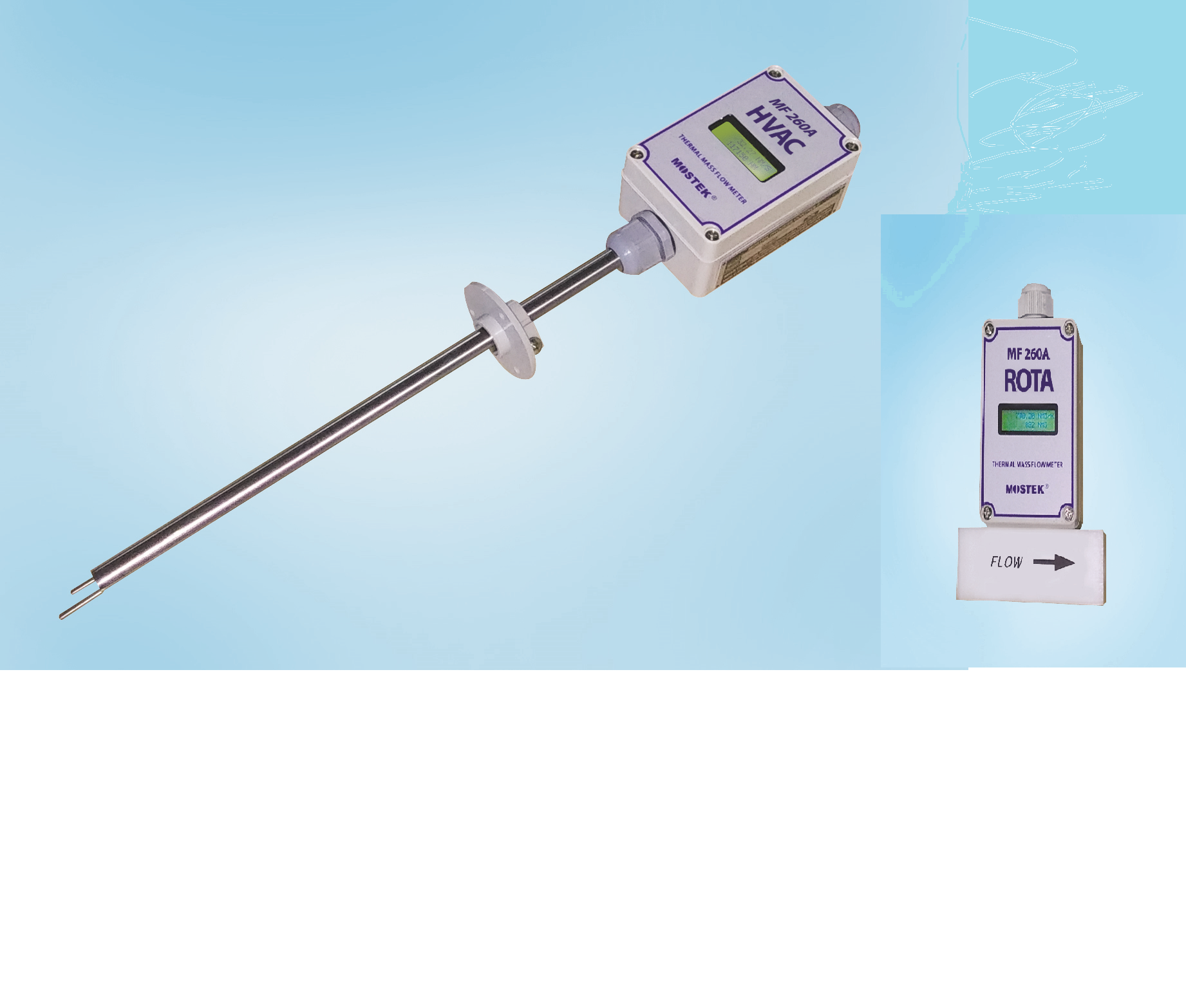
Low Cost of Thermal Mass Flow Meter MF260A HVAC for BAS & HVAC, MF260A ROTA for Rota Meter Replacement |
|
 |
관리자 |
|
 |
2018.11.04 |
 |
1411 |
|
 |
[Feature & Application]
* Low Cost and Compact, Easy installation & Maintenance free
* Flow Monitoring & Control for BAS & HVAC System
* Replacement with ROTA meter with Electronic Signal
* High Accuracy ±1.0% FS
* Output: 4~20 mA, Modbus 485 RTU Digital Communication
* Response Time : 0.9 sec, Repeatability : ±0.2% FS
* Local Display : 16x2 Backlit LCD, Instant Flow & Totalization
* Field Programming with parameter change by Built-In 4-Key
* Low Flow Cutoff Adjustment
[General]
The model MF260A series is designed with full digitally featuring for the measurement of gases, air, compressed air which is based on constant temperature differential technology for air and other process gases. The model MF260A is very suitable for BAS & HVAC as well as ROTA flow which gives simultaneously 4-20mA and Modbus 485 RTU digital communication signal.
Because neither temperature nor pressure measurement are required. MF260A series reduces installation cost and vastly improves system accuracy. The meter is easily installed or retrofitted with minimum down time and provides superior long term process reproducibility and easy serviceability.
MF260A inline type ROTA flow meters are available in probe sizes from 1/4” to 1” with NPTF fitting connection, and insertion type flow meter HVAC is available in probe sizes from 20” up to 150” with flange connection. The MF260A provides a 4-20 mA output signal, and Modbus 485 as a digital communication.
MF260A series flow meter utilizes a constant temperature differential (dT) technology. The sensor has two RTD elements. One is the velocity sensor and the other one is gas temperature sensor. The electronics heats the velocity sensor above the gas temperature as constant differential temperature.
It is the job of the electronics to maintain a constant ΔT between the gas temperature and the heated element.
As the mass flow increases, the increased number of gas molecules remove more heat from the heated element. The electronics senses this temperature reduction and adds additional power in order to maintain a constant ΔT.
The amount of power delivered to the heated element, therefore, is just proportional to the mass flow rate.
[Performance Specs]
* Accuracy
±1.0% Full Scale
Straignt Pipe Run 10 x ID (U/S), 5 x ID (D/S)
* Repetability ....
±0.2% Full Scale
* Response ime
0.9 sec ( 63% one time constant of final value )
* Gases
Air, Argon, Nitrogen, Oxygen, Methane, Propane, Butan,Carbon Dioxide, Butane,
Natural Gas, Digester Gas, Hydrogen, Ammonia, Mixed Gas,Others
[Operating Specs]
* Measuring Flow Units
Nm3/hr, Nm3/min, Kg/day, Kg/hr, Kg/min, Kg/sec ,SCFM, SCFH, Lb/day, Lb/hr,
Lb/min, Lb/sec , NLPH, NLPM, SLPM, SMPS, NMPS, SFPM
* Measuring Flow Velocity
0 ~ 50 NMPS (standard)-based on air @0℃ 1 atm
0 ~ 100 NMPS (option)-based on air @0℃ 1 atm
=====================================================================================
To determine if insertion flow meter will operate, properly divide the maximum flow rate by the duct area. Here are the flow rates for common pipe sizes.
Duct(square)...............Nm3/hr..............SCFM
-------------------------------------------------------------------------------------
* 20 .inch...........0 ~ 45000..........0 ~ 28600
* 40 inch...........0 ~ 185000..........0 ~ 77800
* 60 inch...........0 ~ 418000..........0 ~ 266200
* 80 inch...........0 ~ 743000..........0 ~ 473000
* 100 inch............0 ~ 1161000..........0 ~ 739400
* 120 inch............0 ~ 1673000..........0 ~1065600
* 150 inch............0 ~ 2612000..........0 ~1663600
note : reference gas Air
Standard condition Nm3/hr: 0℃ 1 atm , SCFM : 70°F 1 atm
=====================================================================================
To determine if inline flow meter will operate, properly divide the max flow rate by the pipe area. Refer to the flow table below
Pipe(sch40).............Nm3/hr............... SCFM
-------------------------------------------------------------------------------------
* 1/4 . inch..............0 ~ 13................0 ~ 8
* 1/2 inch..............0 ~ 37...............0 ~ 24
* 3/4 inch..............0 ~ 65...............0 ~ 42
* 1 inch..............0 ~ 105...............0 ~ 67
* 1-1/2 inch..............0 ~ 240...............0 ~ 152
* 2 inch..............0 ~ 394...............0 ~ 250
* 2-1/2 inch..............0 ~ 614...............0 ~ 390
note : reference gas Air
Standard condition Nm3/hr: 0℃ 1 atm , SCFM : 70°F 1 atm
=====================================================================================
* Temperature
Standard Sensor : -40 ~ 80 °C
High Temp Sensor : 0 ~ 120 °C
Enclosure: -40 ~70°C without display
0 ~ 60°C with display
* Power Supply
Standard : 24 VDC 0.2 Amp
Built-in Surge Protection
DC reverse polarity Protection
* Output
4-20 mA DC, Modbus 485 RTU
[ Physical Specs]
* Sensor Material
Standard : 316 Stainless Steel
Option : Hastelloy-C 276
* Enclosure
Weather-proof, NEMA 4X, IP66
Non-hazardous area installation
[Dimensional Specs]
* Probe Diameter : 1/2-inch ( 12.7 mm )
* Process Connection : 1” Plastic Flange or
on request (insertion type)
/////////////////////////////////////////////////////////////////////////////////////
|
|
 |
00-CATALOG-MF_SERIES-EN-2008.pdf |
|
|
| |
 |
|
| |
|
| |
|
| |
 |
 |
12, 166 Bun-Gil, Gahyun-Ro, Tongjin-Eup, Gimpo-City, Gyeonggi-Do 10030 ,korea
Mostek Co., Ltd Registered No : 217-59-00187
Phone : +82-31-982-3909 Fax : +82-31-982-6909
email : info@mostek.co.kr URL : www.mostek.co.kr
Copyrightⓒ 2000 Mostek Co., Ltd. All rights reserved |
|
| |
|